| Installation : | |
| HOW TO: Improve your B&T (Baja Skunkworks) V1 brakes - Cable Mount Modification | |
| One of the important improvements on the V2 brakes over the V1s is the cable grip mount to the calliper assemblies. Of course there are other key ones such as the lever and cable mount assembly, but this thread is to deal with a simple improvement for those with the V1 set up. | |
| The Issues… | |
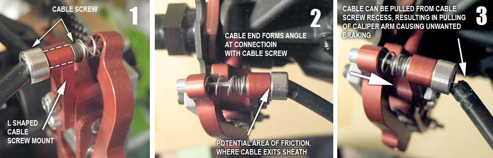
| The cable needs to be a
specific length to allow full movement of your steering action without the
cable end pulling from their housings. Pic 1 - In V1, the cable sheath end slots into a recess (appx 3-4mm) in a screw type housing (part that retains the spring, and in which the cable threads through, which will be referred to as a cable screw). This is the type found on many cycles etc where the alignment of the cable itself is usually linear or parallel to that of the cable screw and/or does not undergo as vigorous movement as on the baja set up (due to steering). |
|
 |
|
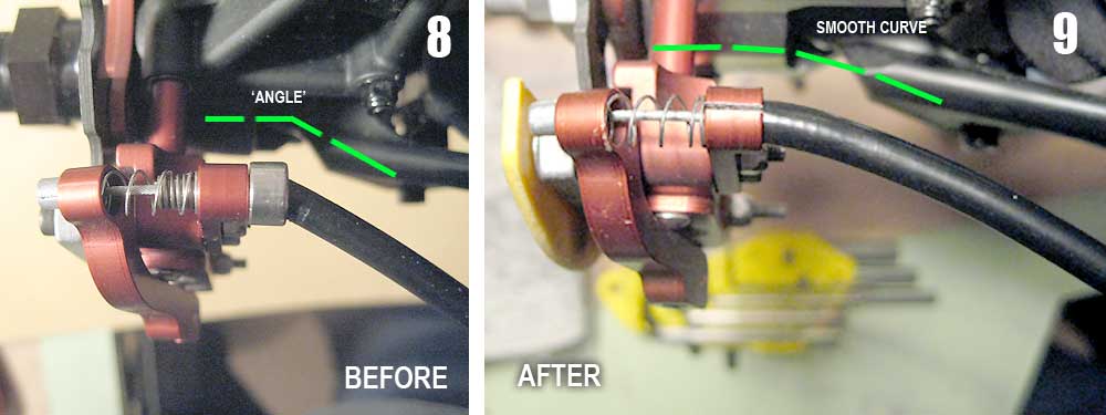
| If not restrained in
some manner – ie such as the clamps on V2, then the sheath will tend to
form an angle, Pic 2 / 8 (rather than a smooth curve when restrained) with
the cable screw. The angle results from a need to keep the length of the
sheath long enough to stop the sheath pulling out of the cable screw on
full steering lock. This angle causes friction at the calliper end. Additionally, if the cable end dislodges from the housing (Pic 3), during normal movement from steering/braking for example, this may result in the cable pulling the callipers, partially engaging the brakes. Both of these issues may impair the full potential of the brakes. My own B&T brakes were installed a while after the installation of the HBZ bumper (see here). As such, the cables were held pretty straight and were also held nicely in the cable screws. The issue went unnoticed until fairly recently when the HBZ bumper was removed. The above ‘angle’ situation became more pronounced as well as the cable end issue. |
|
| Solution - How to… | |
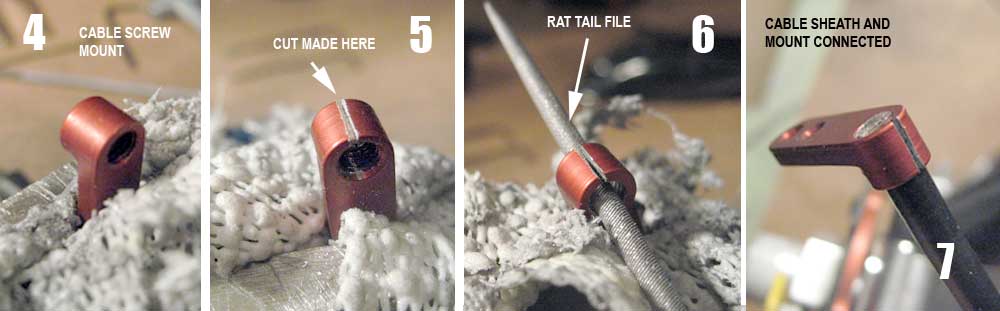
| Remove the L shaped cable screw mount fixed to the calliper, which houses the end of the cable sheath. Remove the cable screw. Protecting the anodizing with a rag (Pic 4) place in a vice and proceed to cut the top portion of the head with a fine hacksaw (Pic 5). | |
 |
|
 |
|
| Remove the cable
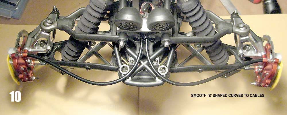
sheath. Carefully use a rat tail file (Pic 6) to file down the threading inside the hole – only a marginal amount is needed. Intermittently check the ID against cable sheath OD. The ID should be tight around the sheath, enough so that a fair bit of force is required to ‘screw’ the cable into the aperture (twist it, while pushing carefully ensuring all of the plastic sheathing is entering the hole evenly) – Pic 7. A small bevel filed around the opening will aid cable sheath entry. Allow the end of the sheath to just protrude past the face of the opening – this will help retain the spring. The cable end is now fully restrained over the 6mm depth of the holder aperture If done carefully you will end up with a fairly discreet but pretty robust connection and an improvement over existing. Smooth curves to your cables Pic 9 / 10. Reconnect the mount – use blue threadlock to secure lower screw, top one will obviously be secured with the nut from one of the brake pad screws. |
|
 |
|
Further Reading; B&T
Super Deluxe Cable Brakes - Installation |
|