| Installation : | |
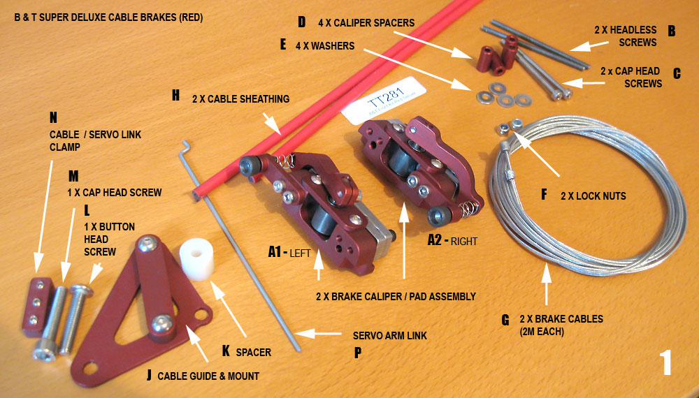
| B&T Super Deluxe Brake installation | |
 |
|
| Super Deluxe kit contents | |
 |
|
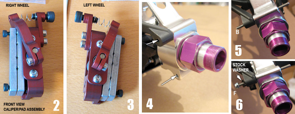
| 4 - Remove the two stock screws(& washers) marked with the arrows (pic 4). Insert headless long screw into top hole (pic 5), placing stock black washer just removed, and lock nut to rear side of hub (pic 6) | |
 |
|
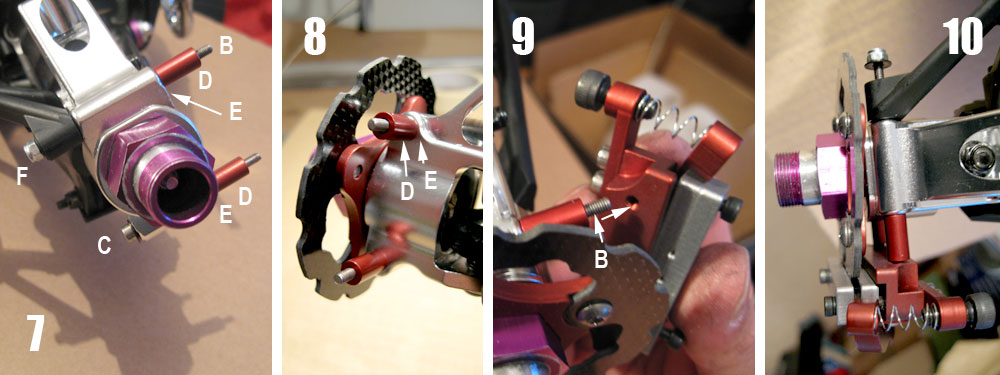
| Insert
long cap screw, C, and stock washer in bottom hole, from rear and place
washer E & cyclindrical spacers on projecting part of the two screws
(pic 7). Place rotor blade onto wheel hex. Offer up caliper assembly (pic 9) to the screw ends, after loosening the brake pad screws to allow free fit of rotor. |
|
| Thread
cable through brake arm on caliper and screw/sping set up (pic 13) What you may notice is that if you tighten the wheel nuts, the brake rotor/wheel may bind with the hub and not turn freely as expected. This is because there is not enough play between the wheel hex and hub housing (pic 11) and may occur, particularly if you’ve done the e-clip mod. In this case you may need to shim it away from the housing using FE Pro series shim kit (pic 12) - probably not as many as Ive shown here diagrammatically. Place cable sheath H on cable G (pic 14, 15) |
|
 |
|
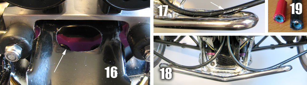
| A
hole dremelled out of the centre of the front body piece (pic 16) is
what I found to work best for free mocement of the cables, eg when full
lock steering etc. The configuration shouldn't be excessively stiff that it hinders the turning motion. Also the cables should be long enough so that they don't pop out of the screw holders at the caliper end (may occur as I trimmed the red ones when test fitting). My preference was for red coloured calipers though did not want to use the red sheaths that came with the kit. These were changed for black 'Jagwire' ones(pic 17). Readily available from bike shops etc - just make sure they are of the internal lined type (pic 19). |
|
 |
|
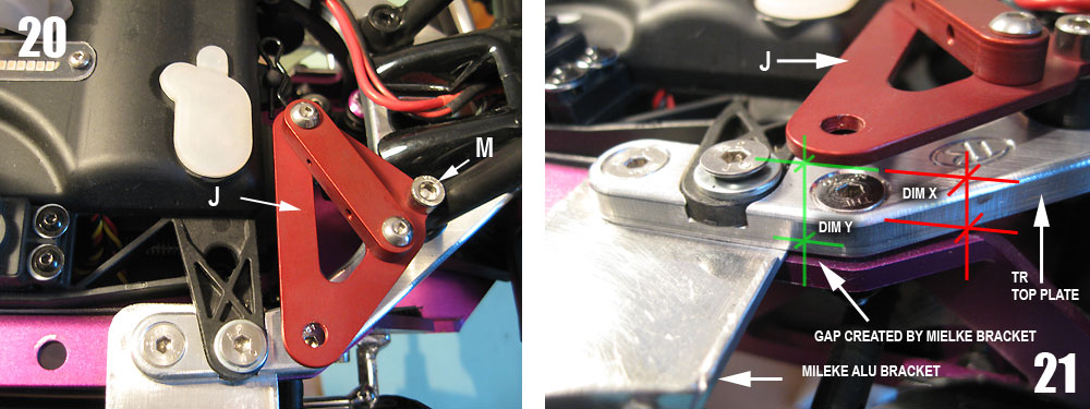
| Position
the cable mount part J and replace the stock screw with the supplied cap
headed screw M in the base of the right side shock tower support (pic
20). You will note that the spacer K may need cutting to the right height, depending on what set up you have, eg whether a TR is in place, and in my case the Mielke bracket (dim x required in my instance - dim Y standard) |
|
| Spacer K cut to size. Spacer fitted with supplied button headed screw L. | |
 |
|
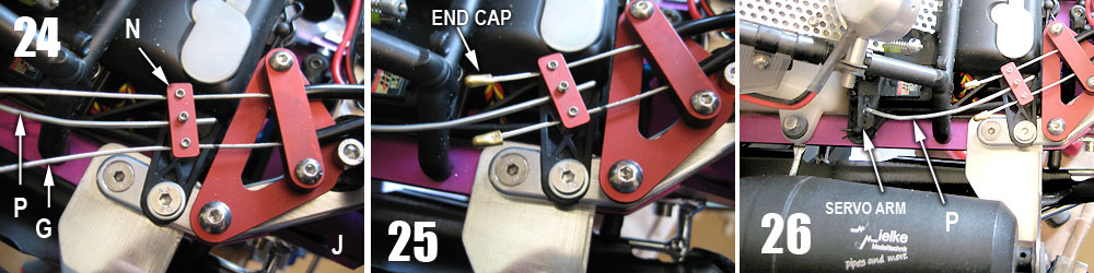
| Insert
the two sheath end into the cable mount J and push cable through (pic
24). Thread through the clamp N. Attach one end of the servo arm link
wire P to the servo arm and insert the other into the central hol;e of
the clamp. The link wire will need to be curved to suit (pic 26) and the
clamp end trimmed. Once the set up is near correct, trim the two cables (each are 2m in length!) and crimp end cap protectors in place (from a bike shop). |
|
 |
|
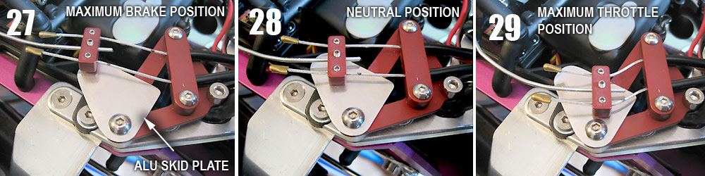
| The
clamp seemed to catch on the edge of the mount (even with bending the
wire at various angles) at full throttle - so I made a skid plate to
keep it level and motion smooth at all positions (pic 27,28,29)
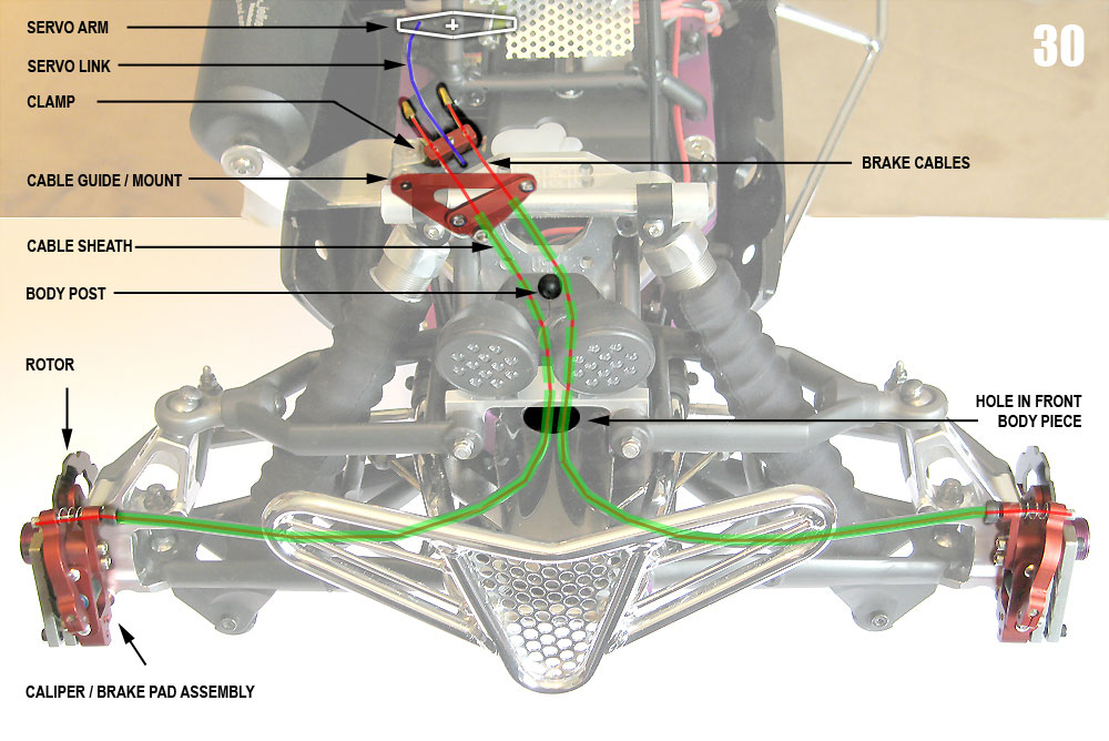
Below - Simplified
diagram of front set up |
|
 |
|
 |
|
| Completed
installation (above) Some fine tweaking will inevitably be required for correct set up. |
|
 |
|
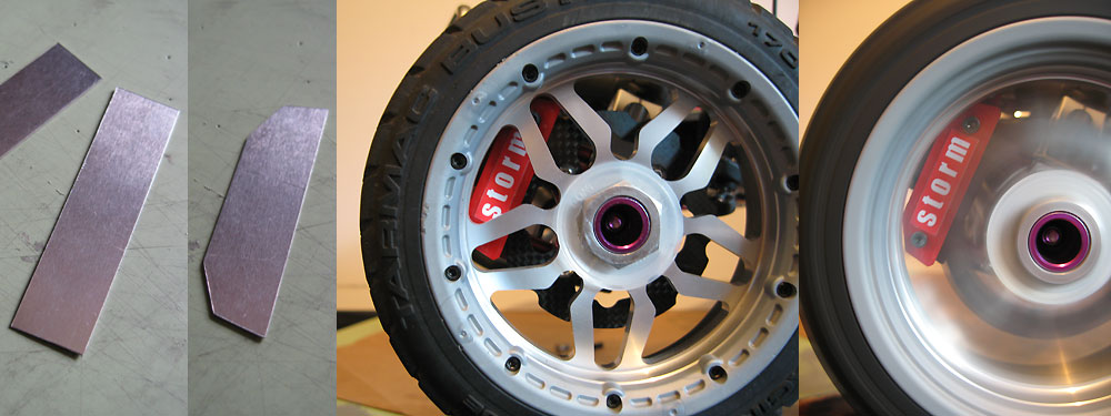
| Custom cover panel to the pads -thin aluminium sheet, primed, painted and stickered up as required. | |
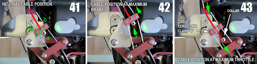
| Additional
set up notes - COLLAR FITMENT OPTIONS OPTION A - (Credit - My1st) |
|
 |
|
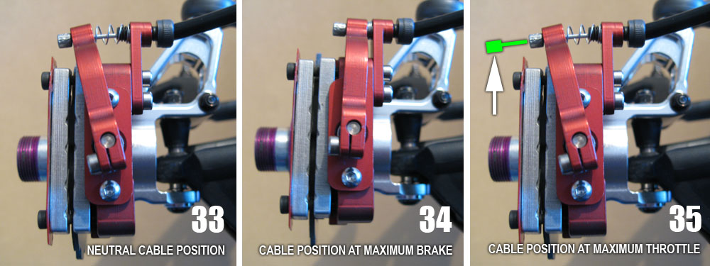
| Under full throttle, the brake cable will naturally move outward toward the inside of the wheel rim, similar to the position shown in pic 35 (green) – and as a result may rub against the rim, hindering wheel movement – not ideal if your at full throttle position. | |
 |
|
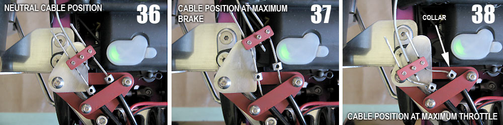
| The
placing of two collars on the cables at the mount location (pic 36, 37,
38 ) will restrict the movement of the cable at the caliper end,
resulting in a position similar to that at the neutral position (pic 33),
thereby preventing any wheel rub. Different set ups may be required, depending on what wheels are being run at the time. Experience to date is with Ramtech billet rims and stock HPI wheels. The reason for the differing set ups is down to the spoke design / wheel section. In section, the Ramtech spokes radiate from the centre (obviously) and gently curve backward toward the inside of wheel, ie they have more reveal (recess) between the spoke end and beadlock. This creates a reduced dimension between the outer face of the calliper assembly and the inner face of the spoke. In section, the stock wheel spokes radiate from the hub but curve outward toward the outer edge of the rim, effectively touching the beadlock, ie they have no reveal. This then creates a greater dimension between the caliper and spokes. Where stock wheels are being used, if the linkage and cable set up is fine tuned, there should be sufficient room that collars should not be necessary. My preference is to run with collars regardless to allow free choice of wheel type. If Ramtech billet wheels of the type illustrated are used, the set up will more than likely need modifying with collars to prevent this outward movement and any rub issues. The now restricted movement of the two cables will cause them to bend sideward more. Compare pics 29 and 38. This may cause part of the mount assembly / cables to touch the inside of the body at full throttle. The mount height itself may also result in the body having a more snug fit, particularly in my case where the Mielke bracket raises the height somewhat (pic 21). |
|
OPTION B (Credit - Allanach Racing) A collar variation -
which will help reduce excessive cable flex / clamp movement (N, part
shown with the three grub screws, labelled 1,2,3 in pic 41) is described
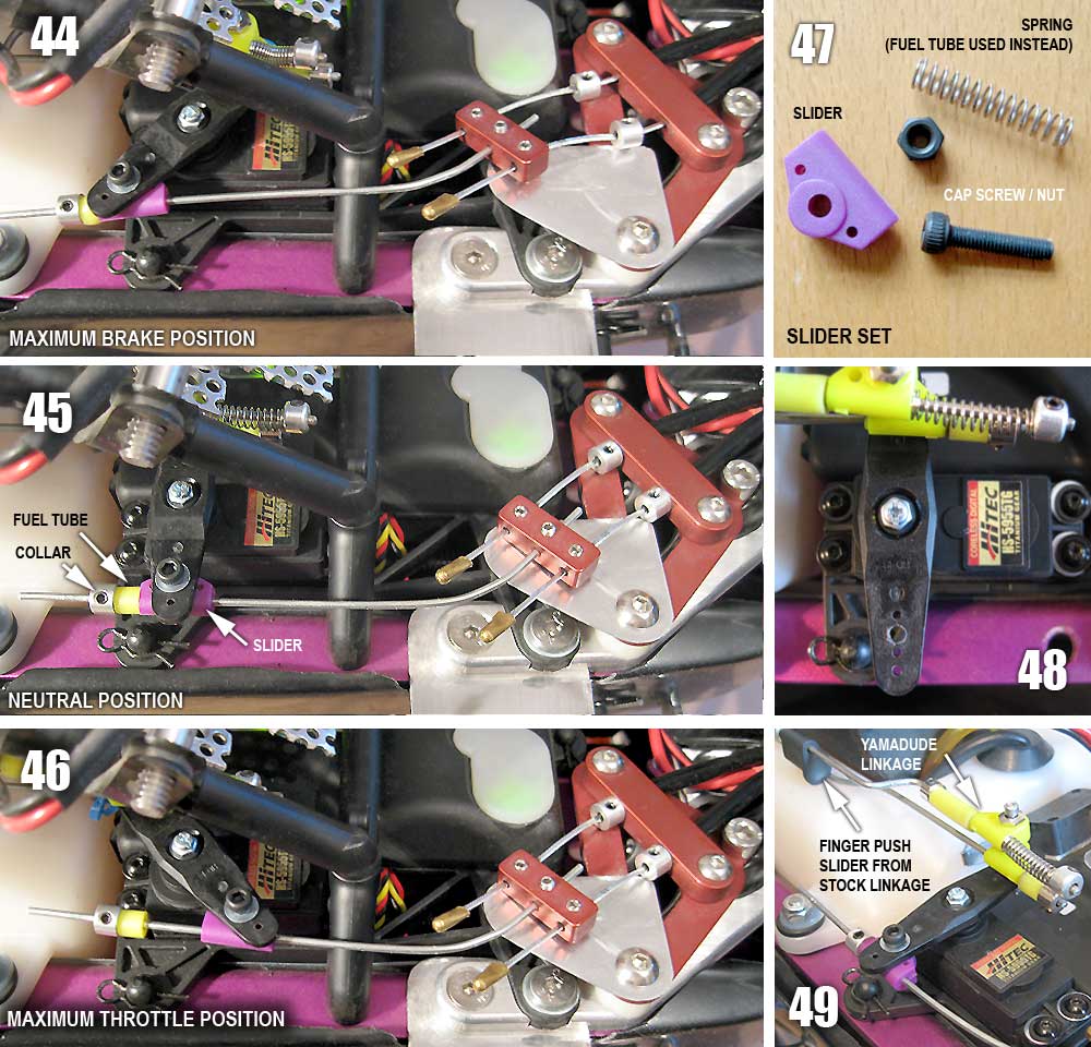
below; As such, another option would be to retain the original position of collars (as Option A) AND use another collar as shown above (pics 41 -43). This would then maintain a fixed cable position at the calipers at full throttle, but allow the servo link wire to slide through the clamp. (credit: Allanach Racing) Other solutions to reduce
cable flex / clamp movement include the fitting of a throttle slider
to the servo arm (credit: My1st) |
|
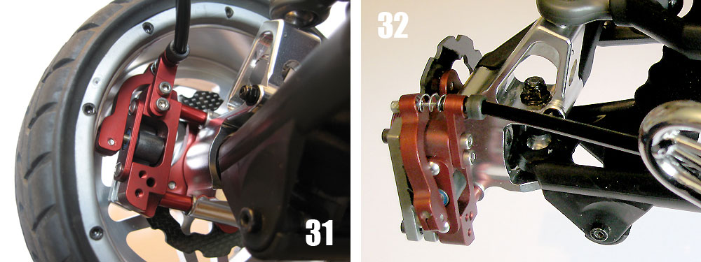
| An additional note re the adjusting screws. | |
 |
|
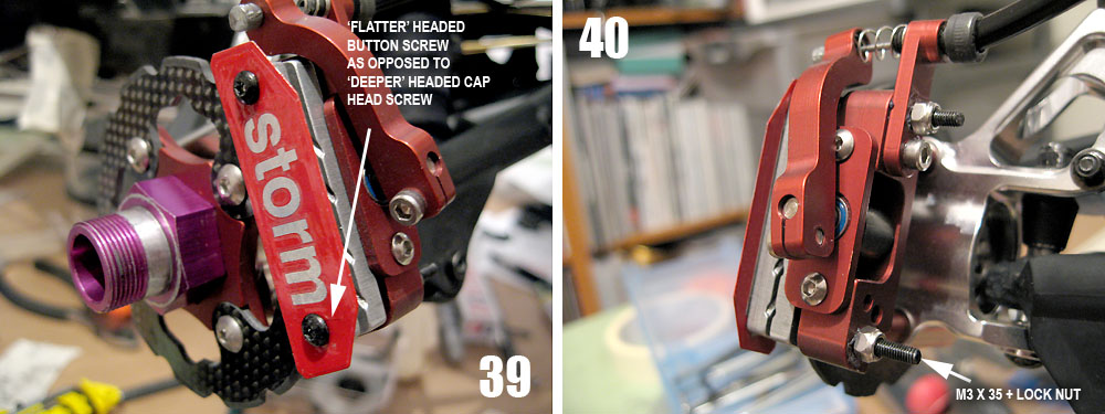
| The
stock brake pad adjusting screws are cap headed M3s. The Ramtech spoke design results in the cap headed screws protruding close to the inside face of the spokes - a little too close for comfort. They are held in with threadlock or similar. During set up the screws were adjusted a number of times and may have resulted in less tackiness. Following initial test runs, one of the screws came loose, locked up the wheel, and the end result was a luckily only a bent screw. Threadlock is great but it is better to leave no room for doubt. As such a change in screw type from a cap headed type to a button headed M3 x 30 or 35mm (35 shown as it was ready to hand) with a lock nut was decided upon. The flatter head design also gives more clearance from the inside face of the spokes than the cap headed screw. The small L shaped cable guide (which holds the end of the sheath, spring screw etc) is held to the main body of the calliper with two silver screws. By removing the upper screw the new longer M3 can be screwed all the way through and 'fixed' with a lock nut. The lower adjusting screw can simply be threaded through with a lock nut. With the lock nuts in place adjustments can still be made and there is absolutely no way for the screws to back out toward the spokes. |
|
Original forum threads and comments detailed at; B&T
Super Deluxe Cable Brakes - Installation |
|