| Installation : | |
| Installing aftermarket Hitec servos | |
| Hitec HS-5745MG - Steering Servo | |
 |
|
 |
|
|
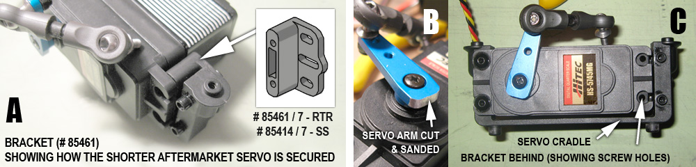
(A) - The adapter bracket required for installing some of the aftermarket servos can be
found within the servo arm set that is included with the RTR (part
# 85461/7) and the steering / servo arm set within the SS kit (part
# 85414/7). The installation diagrams are shown in Section 5, page 48 of the RTR
manual, and Section 7, page 91 of the SS
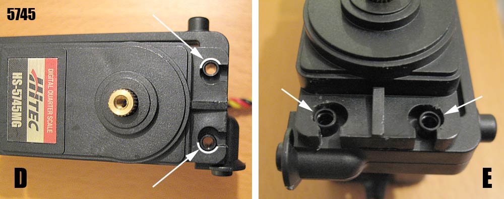
manual. Once assembled in the servo cradle, the servo tabs should align with the adapter bracket holes, ready for screw fixing (C). (D & E) - The screw tabs on the servo horn side may require increasing in size (as highlighted) to allow the projecting screw holes on the servo cradle to fit. The blue aluminium 'double' servo arm, normally included with the 5745 can simply be cut to suit (B) |
|
| Hitec HS-5955TG - Throttle/Brake Servo | |
 |
|
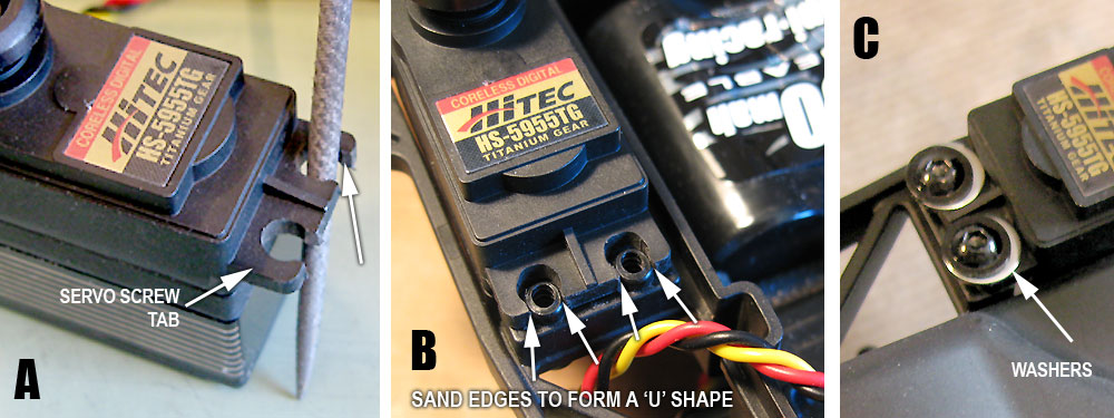
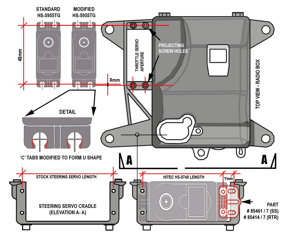
| The length between the fixing point centres is a fraction shorter on
the 5955 servo than those on the radio box servo mount into which the
servo is to be placed. As a result the servo will be prevented from lying flush to the mount unless modifications are made to either the projecting screw holes on the servo mount, or the 'C' shaped tabs on the servo. Option 1 - trim the two corresponding projecting screw holes flush to the servo mount face OR Option 2, gradually file down the 'C' shape openings (A) to form approximate 'U' shapes (at the point marked with the arrows, pic B), frequently checking while filing for a snug fit, to the point when the servo can be pressed firmly into place around the projecting holes (B) A couple of washers (C), if necessary, can be used with the servo mount flanged screws to secure the assembly. |
|
 |
|