| Modification : | |
| A visible engine mounted LED to show status of Diemaster modified Dimension Engineering (1A) Pico Switch / 'Kill switch' | |
 |
|
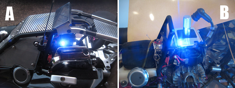
| (A, B) - final location of LED shown mounted in engine shroud. | |
 |
|
| B (above
left) shows the existing pico (the photo shows the protective clear wrap has been trimmed in two
areas exposing the LED terminals - the work can either be carried out
with the wrap in-situ, or in this case, removed and replaced following
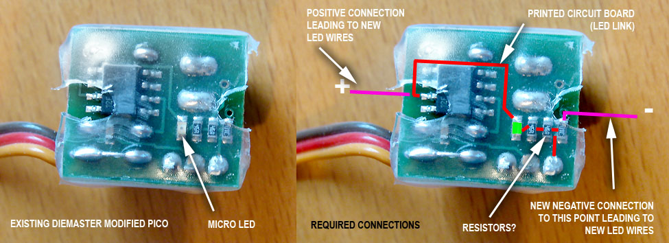
completion of soldering work. C (above right) – shows diagrammatically, the route of the on board LED, and the terminals to which the new extension / LED will connect. The connections require fine soldering work, and with only basic soldering tools to hand, I chose to leave the on board LED intact. The worst I guess that could happen is that the LED would give a bit more resistance to the current. |
|
 |
|
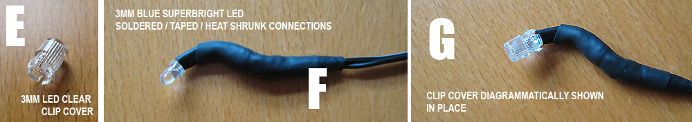
| Items
Items used for this mod - 3mm blue LED, clear 3mm LED clip cover (E). |
|
 |
|
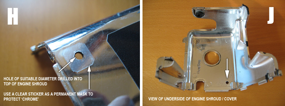
| H – Hole drilled in engine cover, using a clear sticker to guide drill bit/prevent slipping, but also
to act as a permanent mask to the base of the led cover, and flaking of the chromed plastic. Obviously not need if the engine has a black cover. An ideal sticker type can be got from the clear in-between pieces of the sticker sheet that comes with the baja body. J- shows the location of the hole positioned to avoid being too close to the fins, sufficient edge clearance, and the ability to use a body clip for safety (see pics M-T) LED covers come in various designs suitable for different thickness materials, and depending on what type is readily available, you may need to do some additional modifications to the hole to allow it to click firmly into place. |
|
 |
|
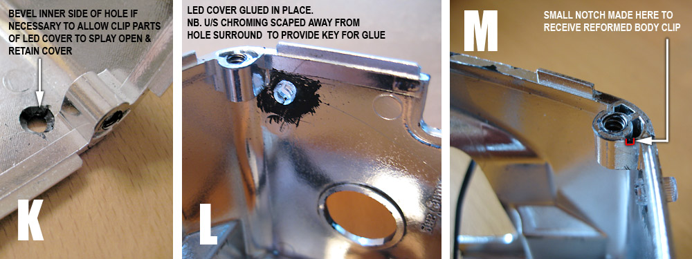
| In this case the engine cover was a little too thick and
the inner side of the hole had to be countersunk the for the splay parts of the
cover to click properly (K) L – Chrome from surrounding area to the inside of the hole was scraped clean to provide a key for the gluing of the cover. Appropriate heat resistant glue was used, eg Evo Stick Serious Glue. M – a little notch (1mm or so) was cut into one of the screw hole zones as shown for a 'safety clip'. Reassurance is given by a mechanical fixing (to avoid anything dangling on to the magneto or flywheel!), as opposed to relying purely on the standard push-clip method of installing an LED into an LED cover. |
|
 |
|
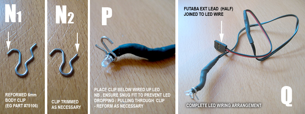
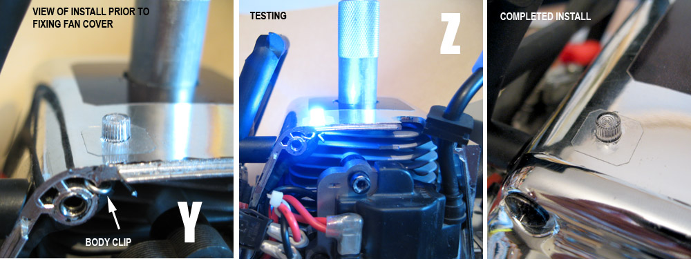
| N – a standard small body clip was reformed and trimmed to act as a 'safety' clip, one end hooked into the notch (which would be securely retained once the fan cover/ screws are in place, T, Y) – the other hooped end holding the led/wire 'neck' position (P) Q – LED wiring made totally detachable. Futaba extension cable cut in half and used for the two connectors |
|
 |
|
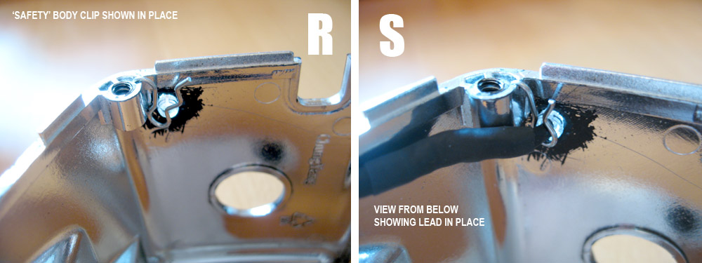
| R – show the safety clip in place, S – shows how it retains the LED. | |
 |
|
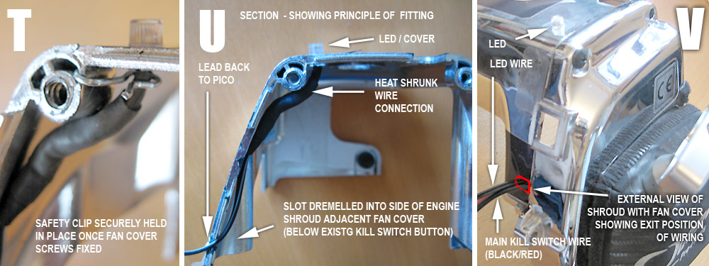
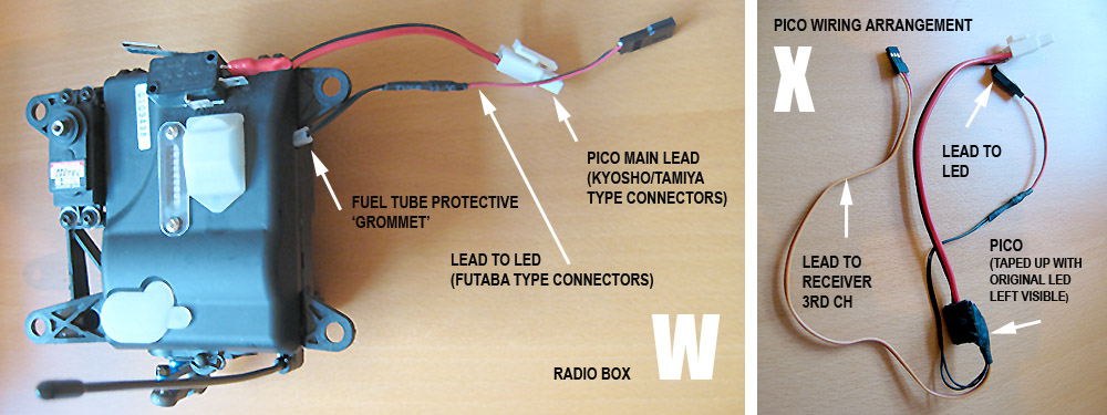
| U – Shows principle of the layout. V – The wires from the LED exit from the same slot in the side of the shroud, as that used by the main kill switch leads. |
|
 |
|
| W –
shows the radio box. The only reason the LED wire exits the box at a different location to that of the main kill switch wires is that
it exits via a hole previously made for another use - there is no reason
why the two can not be combined, if anything it would be preferable.
X – shows the Diemaster Pico, all bandaged up after some minor ops. After the LED wire connections were made to the
pico, the circuit board was covered in glue to provide rigidity to the connections made. The original protective clear cover was put back on, and the whole thing wrapped in insulating tape with a widow cut to view the on board LED. |
|
 |
|
| In conclusion it's a relatively straightforward mod and one that IMO that's worth the effort, not only for the kill status light but also to serve as a reminder power on/off indicator. | |
| Credit
- Wicked{OZ} Original thread detailed at www.hpibajaforum.com/forum/showthread.php?t=24289&highlight=pico |
|